

It’s not instantaneous as the capacitor takes some time to discharge.Īlt Text: 2N3904 Switching Characteristics from the 2N3904 datasheetĪs per the 2N3904 datasheet, the transistor takes 35ns to rise from its initial value to 10 % of its final value (delay time) and also takes the same time from there to reach 90% of its final value (rise time). Switching Characteristicsĭue to inherent capacitance of the transistor (Cce, Ccb, Ceb), it takes some time for the current to rise and fall. If your application is sensitive to this much noise, e.g., RF amplifiers, and you require an extremely quiet device, transistors like 2SC3324 or 2N5088 would be your ideal bet. The term NF represents the internally generated noise by the transistor due to temperature fluctuation, which should be no worse than 5 dB in this case, as per the 2N3904 datasheet. Knowing these maximum input and output capacitance values helps designers to acknowledge the maximum frequency input signal to drive through the transistor to avoid leakage current. Here Cibo and Cobo represent input and output capacitance of the transistor, respectively, in a common base configuration with output open as shown in the image below. That means, at this frequency, the transistor can no longer amplify the signal. Here the term fT represents the frequency at which the output signal current will be equivalent to or less than the input signal current, irrespective of the set amplification. 0.3Vdc when the IC = 50 mA and the base is driven with 5 mA (hFE = 10).

0.2Vdc when the IC = 10 mA and the base is driven with 1 mA (hFE = 10).The maximum voltage drop across the device (Vce) during the ON condition can have two different values as follows: The point of this analysis is to acknowledge the importance of designing the circuit of the transistor for a hassle-free operation despite a high gain bandwidth. The gain at this point is ten times of the minimum gain that the transistor gradually achieves at the end for IC = 100 mAdc at VCE = 1.0 Vdc.

The minimum gain for 2N3904 is 40 for IC = 0.1mA which goes up to max 300 for IC = 10 mAdc at VCE = 1.0 Vdc. You can see the PNP type has 50% less gain than the NPN type- the biggest reason why the NPN type is so popular. The 2N3904 datasheet also lists the DC current gain (hFE) of its alternative 2N3903 (PNP) in separate rows. The table below shows the ON characteristics of 2N3904. Now let’s take a look at the gain table of the device. The power dissipation is in milliwatts, clearly showing that the device is not designed for high-power applications. The 2N3904 transistor has maximum ratings, as shown in the table below.Īs you can see, the transistor can conduct a maximum 200mAdc with a maximum input voltage of 6 Vdc applied between base and emitter. 2N3904 Datasheet Analysis Maximum Ratings
#2n 3904 datasheet how to#
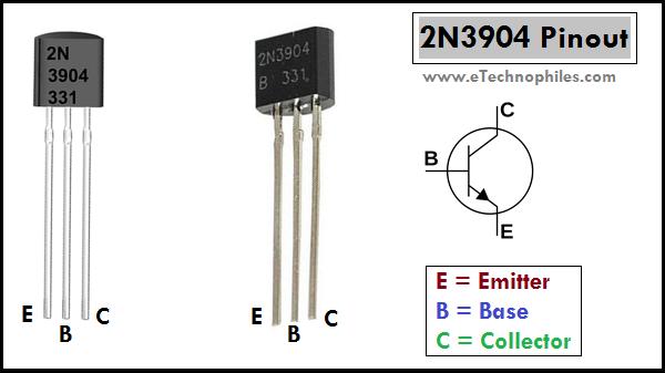
Knowing how to read the 2N3904 datasheet helps engineers better design it for reliable amplification and switching applications. It is an NPN BJT transistor yet comes in PNP configuration (2N3906) as well. The 2N3904 is a small signal transistor, registered by Motorola in the mid-1960s, used for general purpose switching (100 mA) and amplification (100 MHz) applications. A small signal transistor is designed for applications dealing with low voltages and currents, definitely not for power amplifiers.


 0 kommentar(er)
